Introduction
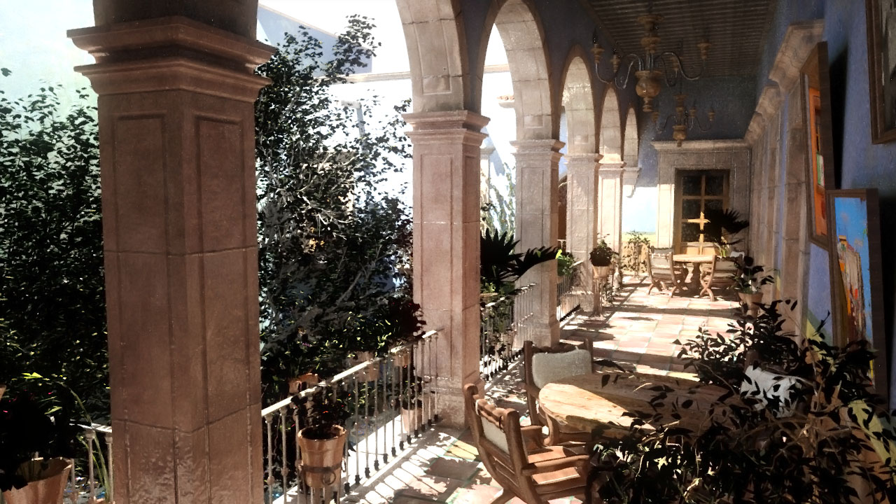
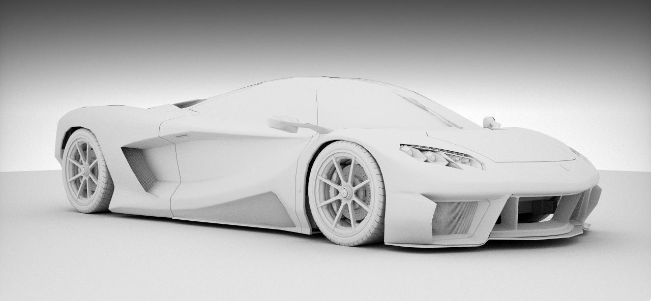
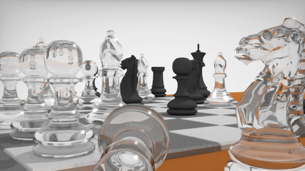
In this project, you'll implement an elegant and relatively efficient path tracer for producing photorealistic images similar to Figure 2. This will combine high-performance CPU programming techniques and a sophisticated mathematical integration technique. This is the actual algorithm used for most preprendered computer generated imagery today, including both live-action special effects and animated films.
You can see the image quality for yourself. For performance, consider that my Rays project renderer took 13 minutes to render Sponza at 640×400 with direct illumination only. Yours was probably similar. In this new Paths project, my renderer takes about 15 milliseconds to render the same image on the same computer (and yours is required to be under one second). That's a speedup of about 50,000x for a program with the same code side!
Prerequisites
- Complete the Rays project
- Read in the Graphics Codex:
- The Rendering Equation
- Materials
- Rendering Algorithms
- Path Tracing
Educational Goals
- Implement the complete and fundamental rendering algorithm
- Gain experience with a high-performance ray casting library (and the constraints it imposes)
- Learn discrete importance sampling by implementing it yourself
- Structure a complex program for high-throughput computing
- Experimentally validate correctness, image quality, and performance of your implementation
Rules for this Project
You are not permitted to look at the pathTrace G3D sample program or the source code for
G3D::PathTracer, or use G3D::PathTracer in your solution.
Path Tracing
Path tracing is a family of techniques first introduced by Kajia in “The Rendering Equation” [Kajiya86]. All path tracers converge to a numerical solution to the radiance equation [Immel86],
\begin{equation} \Lo(X, \wo) = \Le(X, \wo) + \int_{\mathbf{S}^2} \Li(X, \wi) \cdot f_x(\wi, \wo) \cdot |\wi \cdot \n| ~ d\wi. \end{equation}
They do this by combining three ideas:
- Recursive ray tracing [Whitted80] in which the paths of photons are traced backwards from
the eye through the scene.
- The observation that the best way to sample a high dimensional space (in this case, light transport
path space) is to sample across all degrees of freedom simultaneously [Cook84].
- Importance sampling increases convergence and fixing the path branching factor at unity makes path-space sampling scale well [Kajiya86].
The path tracer for this project uses explicit point lights for direct illumination, but also can compute indirect illumination from emissive surfaces as well. It is remarkably similar to what Kajiya first described, but is extended with full importance sampling of the scattering-function.
High-Throughput Computing
Your path tracer will be thousands of times faster than the ray tracer you wrote for the Rays project. You'll use this performance to tackle much more complex scenes and produce realistic illumination effects within them.
The performance comes from multiple sources:
- Algorithmic improvement of importance sampling: preferentially measure transport on the rays likely to affect the image
- Improved cache behavior through grouping tasks on similar working sets
- Single-instruction multiple-data (SIMD) parallelism within the ray caster
- Approximately logarithmic running time for the ray cast using a bounding volume hierarchy (analogous to a binary search tree for triangles in 3D)
You also will retain the GPU post-processing and multithreading from the Rays project.
Rules for this Project
There are no limitations for this project, beyond the obvious: don't just copy a path tracer that you found elsewhere online. You may look at any G3D sample program or any part of G3D, and I encourage you to do so. In fact, you may even look at any path tracer you find elsewhere for reference (the PBRT one is particularly nice), but be careful—there's a lot of math involved in a path tracer, and tiny changes can dramatically affect correctness.
Specification
Implement a path tracer with the following properties by refactoring the Rays project to/with:
- A user interface for specifying:
- The number of light transport paths per pixel
- The maximum number of scattering events (internal light transport path nodes)
- A button for launching rendering
- Progress updates (
G3D::debugPrintfto the console is sufficient) - The total time spent rendering (as a
G3D::GApp::showwindow title is sufficient)
- Batch-processed CPU multithreading with barrier synchronization, where all rays are traced
in parallel, shaded in parallel, and then scattered and re-launched. This program must
trace Meinl's Sponza at 640×400 with one path per pixel and one scattering event in less
than one second (excluding scene load and tree build time).
- Use a library-provided spatial data structure (i.e.,
G3D::TriTree) for accelerating ray intersection and a library-provided importance-sampled scattering function (i.e.,G3D::Surfel::scatter) - Emissive, direct illumination from point sources at finite locations, and indirect
illumination terms, with only one recursive indirect ray cast per path node.
- Post-processing including gamma encoding (e.g., via
G3D::Film::exposeAndRender) - Importance sampling of direct illumination lights, with only one light sampled per path node.
Report
- Design: Summarize your implementation design in no more than two paragraphs. Provide sufficient
information to aid future implementors seeking to reproduce your work. Why did you make the
program this way? What were your main iteration structures? What were the key
G3D routines that you used?
- Correctness: Demonstrate that your program is functioning correctly by rendering the following images.
Render them at 320×200 so that you don't have to wait too long. (You should do this as
you are implementing, since if there are bugs, these images will help you to identify them):
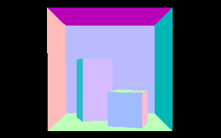
- Eye ray directions (in world space) visualized as colors by \vec{c} = (\w + 1) / 2 at \gamma = 4.4
- World-space hit positions visualized as colors by \vec{c} = P \cdot 0.3 + 0.5 at \gamma = 4.4 for the Cornell Box
- World-space geometric surface normals visualized as colors by \vec{c} = (\n + 1) / 2 at \gamma = 2.2 for the Cornell Box
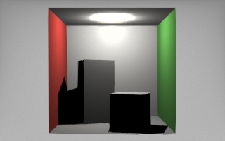
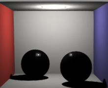
- Rendering of the Cornell Box with one path per pixel and a maximum of one scattering event
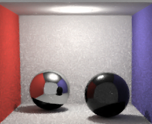
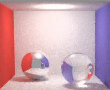
- Rendering of a box with a perfect mirror ball and a glass ball with 128 paths per pixel and a maximum of one scattering event
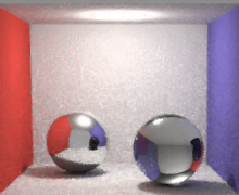
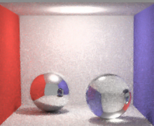
- The box from the previous image at 2, 3, 4, and 10 scattering events. Note that it takes
four scattering events to produce a caustic.
- Performance: Show a graph of rendering time for Sponza at 640×400 (use the same viewpoint from
your Rays project so that you can compare them) vs.:
- one path per pixel and scattering depth of 1, 2, 3, and 4
- scattering depth of one and 1, 4, 16, 256, and 1024 paths per pixel
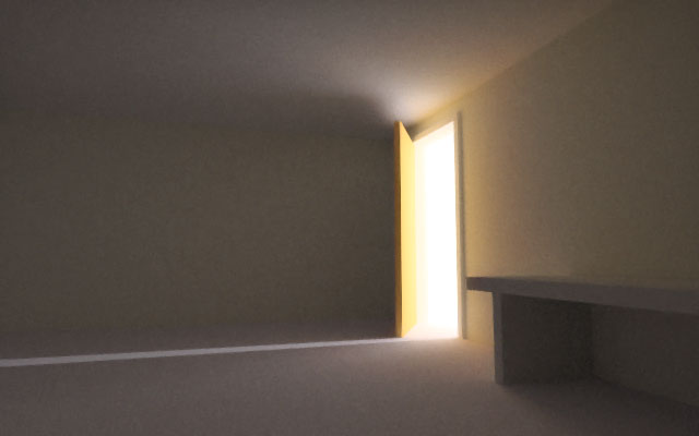
- Quality Demonstration Image: Render one image at 1280×720 that is nearly converged of
indirect illumination in an architectural scene, such as Sponza atrium, Sibenik cathedral,
San Miguel, or even simple boxes arranged in a way that feels like buildings, walls, or
furniture.
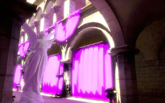
- Phenomena Demonstration Images: Render four images of easy-to-interpret scenes
at 640×400 that demonstrate global illumination effects, such as caustics, diffuse
interreflection, soft shadows, ambient occlusion, mirror reflections, and refraction. These
can be somewhat noisy but the features should be clearly visible.
- Questions: Answer these questions in a paragraph each:
- Why does it take four scattering events to produce a caustic? Give a diagram
or otherwise explain what those events are.
- Derive an asymptotic bound on the run time of the global illumination renderer from the
Rays project, were it to recurse to an arbitrary path depth. Recall that it traced one
primary ray per pixel, computed direct illumination from all sources, and then spawned
r recursive rays. Use the variables: n pixels, d maximum path depth, p primary
rays per pixel, L lights in the scene. It may help to draw a tree of the recursive
calls.
- Derive an asymptotic bound on the run time of the path tracer from this project using the
same variables from the previous question.
- Derive an algorithm to sample the integers from 0 to 100 proportional to their value.
For example, zero will never be returned, two will be returned twice as often as one, 100
will be returned twice as frequently as 50, and so on. Assume that you already have a
uniform real-number random number generator on the interval [0, 1].
- In your own words (and with equations and diagrams as needed), present an mathematically
rigorous argument that path tracing as presented in this project converges to a true
solution to the rendering equation as the path length and number of paths per pixel
approach infinity. State any assumptions underlying that argument explicitly.
- Why does it take four scattering events to produce a caustic? Give a diagram
or otherwise explain what those events are.
- Self Review: Give yourself a nominal grade on this project (A+ through F) and critique your
work in one sentence each on: code design, code readability, expected code correctness,
report writing and presentation quality, expected report correctness, and workflow as documented
in your journal.
- Skills: Describe what you learned while working on this project. Distinguish software
engineering, algorithmic, and mathematical skills. Include the reading and ideas that you
had to implicitly work through even if not required.
- Time: How long did the project take you, from start to finish (excluding time spent reading, including time writing the report)? Distinguish time to the minimum viable product vs. polishing time. Report this as two numbers, in hours.
Example Correctness Results
|
|

|
|
|
|
 (direct light)
|
|
|
|
|
Example Demonstration Images
Advice
You wrote almost all of the radiometry logic for this project when working on the last, indirect light, step of the Rays project. Most of this project is about making that code scale: to more lights, more triangles, more rays per pixel, more scattering events per path. Plan to spend most of your time on the implementation refactoring your old code into multithreaded loops over arrays rather than writing new rendering code from scratch.
Delete your ray-intersection code from the previous project. You don't need it. G3D provides
all of the intersection code this time around. The
G3D::TriTreeBase
abstract base class gives the interface for ray casting and the G3D::TriTree class is a
concrete implementation with fast triangle intersection. (It is actually a typedef for
different implementations on different platforms.) Remember to check isNull(surfel) whenever
you pull a surfel out of your ray cast result buffer produced by G3D::TriTree, since rays can
miss the entire scene if they escape to the “sky”.
Since you don't want a name conflict with G3D::PathTracer, keep your class named RayTracer
or call it something like MyPathTracer.
Workflow
A lot of this project is about refactoring code, which is a key software development practice. Restructure the program in small passes and stabilize it between changes. Do this even if it means writing code that you're going to rewrite again in a few minutes. It is easier to fix mistakes and keep track of what is going on when you work incrementally. And getting something right the first time is better than spending hours debugging it later.
The order that I recommend for morphing your ray tracer into a fast path tracer is:
- Replace your explicit triangle intersection code with
G3D::TriTreesingle-ray intersection calls - Convert to the path tracing algorithm without modifying the essentially serial, recursive
nature. That is, this version should exhibit:
- Multi level recursion for indirect light (the ray tracer stopped at one recursive call)
G3D::Surfelscattering instead of uniform scattering- Only one indirect scattering event (instead of the loop from the Rays project)
- Multiple rays per pixel averaged together
- Direct illumination from all point lights
- Invert the loop structure so that you're iterating over rays per pixel and working with
large buffers. Switch to
G3D::TriTreebatch-intersection calls. You can useG3D::runConcurrentlyfor the inner loops. - Switch from using all light sources at each node for direct illumination to a single
light source chosen uniformly: p(j) =
1 / numLights. - Implement importance sampling for the direct illumination light: p(j) = \frac{\beta_j}{\sum_k \beta_k}
The last two steps require the least code but are perhaps the easiest to make mistakes in and the hardest to implement (in terms of thinking about the mathematics). Leaving them until last ensures that most of your specification-oriented work will be working as soon as possible.
Parallelism
You'll have a lot of code that looks like this:
runConcurrently(0, surfelBuffer.size(), [&](int i) {
    const shared_ptr< Surfel >& surfel = surfelBuffer[i];
    if (notNull(surfel)) {
        Random& rng = Random::threadRandom();
        ...
    }
});
and
runConcurrently(Point2int32(0, 0), Point2int32(width, height),
    [&](Point2int32 point) {
        ...
    });
Recall image layout: the pixel at x, y is at index = x + y * width. This allows you to go
back and forth between loops that iterate in 2D over pixels and the 1D buffer data structures.
Design
The Rays project processed each path on its own task, from primary ray through to light source. That use of purely thread concurrency is inefficient on a modern architecture. Both CPUs and GPUs are capable of single-instruction multiple-data (SIMD) parallelism as well as task (i.e., thread/core) concurrency. SIMD parallelism requires performing the identical operation on a buffer of data in lockstep. Hitting radically different points of a task on one thread (e.g., shading vs. ray casting) also hurts cache efficiency.
This project therefore casts all rays and finds their intersections before shading any. Every step proceeds in this way. In order to carry data between stages, you'll need a number of large arrays that I'll call “buffers” for this project. These are structurally parallel to the final image: all buffers have the same length, and it is equal to the number of pixels.
The buffers that I used were:
modulationBuffer(Color3)How much the surfaces between the eye and the current path node have already modulated the contribution observed due to the BSDF. Initialized based on the number of rays per pixel.
rayBufferThe path rays
surfelBufferSurfaces hit, or
nullptrfor missed raysbiradianceBufferBiradiance due to the selected light, assuming it is visible, weighted by the importance sampling inverse relative probability of having sampled this light. The actual light position is implicitly encoded in the
shadowRayBuffer.shadowRayBufferVisibility test rays for the corresponding lights in the
biradianceBuffer.lightShadowedBufferTrue if the surface is in shadow from the selected lights, false otherwise.
def traceImage(radianceImage, camera):
    if thescene changed:
        extract surfaces from the scene
        rebuild the tree

    // All operations act on all pixels in parallel
    set the image to all black

    repeat for the number of paths per pixel:
        generate primary rays
        initialize the modulationBuffer to Color3(1 / paths per pixel)


        repeat for the number of scattering events:
            intersect all rays, storing the result in surfelBuffer

            add emissive terms (use the sky's radiance for missed rays and
                apply the modulation buffer)

            if there are lights:
                choose which light to sample, measuring biradiance and
                   computing a shadow ray

                cast all shadow rays
                shade all hit points

            if not the last iteration:
                scatter the rays, multiplying the modulation buffer by
                   the scattering weights
In my implementation, almost every one of those steps becomes a helper method of
about five lines of code, containing a concurrent iterator. The intersection
is entirely handled by the various intersectRays methods on G3D::TriTree,
which happen to (by design) have exactly the signatures that you'll need.
Discrete Light Importance Sampling
In a scene where there are a lot of lights, importance sampling based on the potential contribution of the light at the surface is actually a very good strategy. Consider 100 equally bright lights in a grid, where each one barely illuminates the area under the next. At any point, I should spend most of my time sampling the light that is right next to the surface, not the 99 that contribute negligible amounts to the final image. I can get a 100x speedup by importance sampling with only a slight increase in variance (noise) in the final image for the same number of ray casts and shading operations.
As an extreme example, the G3D Cornell box is modeled with six pyramidal spot lights instead of one omni light. This is so that the real-time shadow maps only have a 90° field of view and minimize perspective distortion. If you sample only one light uniformly, you get horrible noise: 5/6 of the time, there's no contribution because the target is outside of the light's pyramid. If you sample all of the lights, you just run 6x slower because 5/6 of the time you compute zero. If you importance sample, you always choose the light that contains the point in its pyramid, so you get the quality of sampling all but the speed of sampling one.
Light importance sampling requires you to compute the biradiance at the surfel location due
to each light (i.e., just invoke G3D::Light::biradiance). Then, select a light with
probability proportional to its biradiance contribution, and weigh it by the inverse
probability of selecting that light.
The easiest way to do this is to intialize a counter to a random number between zero and the total biradiance (I just summed all three color channels) of all lights relative to this surfel. Then, iterate through the lights, decreasing the counter by the biradiance of each light. When the counter becomes negative, select the light for the current iteration.
The weight for importance sampling is one over the probability with which the light was sampled. So, in a scene with a light contributing 20 W/m2 biradiance at a point and one contributing 10 W/m2, we select the first light twice as frequently, but divide the resulting biradiance by 2/3 (i.e., multiply it by 1.5) to account for the other light that wasn't sampled. When we sample the second light, we divide by 1/3 (i.e., multiply by 3) to account for the infrequency of sampling that light and the unsampled, brighter first light.
Note that each surface point (which is in its own pixel) potentially may select a different light to sample.
Implementation
For performance:
- Be sure to pass those large array buffers as
const Array< X >&so that they aren't copied! - Flag coherent casts (the primary rays) as
G3D::TriTreeBase::COHERENT_RAY_HINT - Track
m_lastTreeBuildTimeand only rebuild whenmax(m_scene->lastEditingTime(), m_scene->lastStructuralChangeTime(),m_scene->lastVisibleChangeTime()) > m_lastTreeBuildTime. When the scene is set, force a build withm_lastTreeBuildTime = 0. - If the scene only has one light, choose it. Don't run the full importance sampler to come to the obvious conclusion.
- Cast shadow (visibility test) rays from the light towards the surface
- Flag your shadow ray casts with:
TriTree::COHERENT_RAY_HINT | TriTree::DO_NOT_CULL_BACKFACES | TriTree::OCCLUSION_TEST_ONLY - There's some overhead to casting rays. When working with larger images, your path tracer will get faster per pixel. So, rendering twice as many pixels will take less than twice as long, and large images aren't quite as scary as they seem.
- Avoid memory allocation in kernels. If you must allocate heap memory (e.g., for the
biradiance array when importance sampling), consider using either
G3D::SmallArrayorstatic thread_localstorage on aG3D::ArraywithfastClearto avoid freeing the underlying memory between operations.
For image quality:
- Remember to retain all of your post-processing (Film::exposeAndRender) code from the Rays project
- Remember that the default scene cameras are going to be too “bright” because they are tuned for real-time rendering without indirect lighting. The path tracer roughly doubles the amount of light in most scenes when run with a large scattering depth. Change the camera sensitivity to 0.5 or lower to get better results for path tracing.
- Cast shadow rays towards and recursive rays from a point slightly above or below the surface, based on the
surfel->geometricNormal. For shadow rays, this is justsurfel->position + surfel->geometricNormal * epsilon. For recursive indirect rays, it must be on the side determined by the outgoing ray:rayBuffer[i] = Ray::fromOriginAndDirection(surfel->position + surfel->geometricNormal *epsilon * sign(w_o.dot(surfel->geometricNormal)), w_o), which works for both transmitted and reflected rays. - Assign some nonzero radiance to rays that miss everything in the scene and “hit the sky”. I used the constant
Radiance3(0.5f, 0.5f, 0.5f), which gives a flat gray background. You could substitute the gradient that you designed in the Rays project for slightly more interesting lighting.
For thread safety:
- Preallocate all buffers before launching any threads. If you resize a global array on each thread, then there will be a race condition.
- Use
G3D::Random::threadCommonto access a pseudorandom number generator that can be efficiently used on each thread. This must be called on the thread that wants to use it. Don't fetch the instance for each random number call, just once at the top of your lambda expression - There is no need to protect the
G3D::Imageobject with a mutex, provided that each thread only writes to the pixels assigned to it and there are barriers between tasks. The design described in this project follows those restrictions. - Don't mutate any global state from inside of your
runConcurrentlycalls, except for the image and buffer elements for the current iteration index.
Debugging and Workflow
- Assume that all lights are at finite locations (
light->position().w == 1) - Always cast all rays. If a ray is absorbed or there is no light, create a tiny degenerate ray
- Plan on spending 5% of your time sketching a draft implementation in pseudocode, another 25% turning that into legal code, and 70% of your time testing and debugging. Then, expect to spend hours rendering results, unattended.
- When casting only one ray per pixel, always put it in the center of the pixel. This makes debugging easier, but also makes the image look better when at low ray counts.
- Remember that the G3D Cornell Box is modeled with five lights (for reasons that will be clear later), so with only one ray per pixel, 4/5 of the rays will generate no light.
- For your first draft, choose the lights uniformly at random, so each has prob(1 / numLights). Once you have that working, tackle the importance sampling
- This is the kind of program where it is actually easier to implement the entire thing from theory before debugging
- Visualize intermediate results (Figure 1). Set the radiance equal to the primary ray direction, the surface normal for the first hit, etc. Turn off bloom, vignetting, and antialiasing when you do this, and cast only one ray per pixel with one scattering event.
- When making a lot of sliders with long captions, first do
debugPane->setNewChildSize(500, -1, 300); - Preview images with a small number of rays per pixel and low resolution before launching an hour-long rendering job.
- You spent a lot of time writing this renderer, and it takes very little of your time to produce new results. Make a lot of pictures, to justify your time investment!
- Use
G3D::Image::incrementto update the radiance buffer
for (Point2int32 P(0, 0); P.y < radianceImage->height(); ++P.y) {
    for (P.x = 0; P.x < radianceImage->width(); ++P.x) {
        radianceImage->set(P,
           Radiance3(rayBuffer[P.x + P.y * radianceImage->width()].direction() *
                     0.5f + Vector3::one() * 0.5f));
    }
}Gallery
For more inspiration and some impressive extensions to the base specification, look at some examples of work created by my students for this project:
- Williams College CS371 2016
- Williams College CS371 2014
- Williams College CS371 2012
- Williams College CS371 2010
Graphics Codex Projects © 2018 Morgan McGuire

This document is written in Markdeep to make it easy for teachers to modify it for use in their own courses. Just view the source in a browser and then save it.
All C++ and GLSL source code in this document is released into the public domain to avoid IP concerns on your own project solutions. That code may be used in any project, including commercially without attribution.
Images by others, the G3D Innovation Engine, the Graphics Codex are not covered by this document's copyright and license.
Images with citations are property of their respective owners.
The G3D Innovation Engine © 2000-2018 Morgan McGuire, available under the 2-clause BSD license.
The Graphics Codex © 2011-2018 Morgan McGuire. All rights reserved.